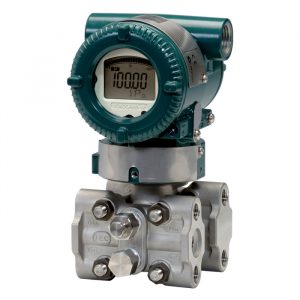
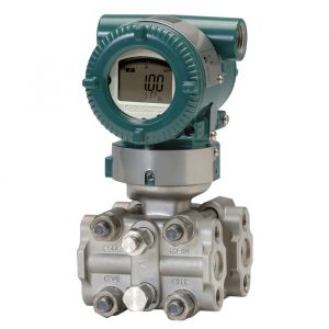
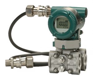
Differential Pressure Transmitter
Differential pressure transmitters are used to measure the pressure difference between two points in a system. These instruments are ideal for applications such as flow measurement, filter monitoring and level measurement in closed tanks. Our differential pressure transmitters deliver high accuracy and stability, even under extreme conditions, making them a reliable solution for process monitoring in critical environments.

More information
How does the measuring principle of a differential pressure transmitter work?
Two pressure chambers and a membrane
A DP transmitter has two separate chambers (high-pressure HP and low-pressure LP), both in contact with the process. The chambers are separated by a very thin, elastic membrane. When pressure difference ΔP = PHP - PLP occurs, the diaphragm bends proportionally towards the lower pressure side.
Transmission to the sensor element
The movement of the diaphragm is mechanically transmitted to a sensing element cell inside the transmitter via an incompressible filling fluid (usually silicone oil) or a direct-coupled mechanism. The design insulates the sensitive sensor from aggressive media and high impact pressures.
Conversion to electrical signal
Two main principles dominate:
| Sensor principle | How the signal is created | Strength | Weakness |
| Capacitive | The diaphragm forms a moving capacitor plate; the capacitance change is proportional to the displacement of the diaphragm | Very low long-term drift, high resolution | Shock pressure can affect accuracy if not compensated |
| Piezoresistive | Strain-gauges (in silicon) change resistance when the membrane is stretched | Wide temperature range, resistant to pressure shocks | Slightly higher zero drift |
Less common variants are resonant crystals or piezoelectric elements that measure frequency changes.
Signal processing and compensation
The analogue sensor signal is digitised by a microprocessor that linearises the curve and corrects for temperature, back pressure and filler density. Advanced models have in-built temperature and set pressure sensors for real-time compensation, greatly reducing the overall error. bcstgroup.com
From ΔP to process size
- flow: Bernoulli's equation relates ΔP across a restriction element (orifice, venturi) to mass or volume flow.
- Level: In closed vessels, ΔP corresponds to the hydrostatic pressure of the liquid column.
- Filter status/pump monitoring: Increasing ΔP indicates clogging or cavitation.
Important factors when choosing a differential pressure transmitter
| Factor | Why it is important | Guideline / Checkpoint |
| Measurement range & turndown | Too large an area → low resolution; too small → risk of saturation | Design so that the maximum expected ΔP is around 70 % of the sensor upper limit. Turndown up to 100:1 is common but gives worse uncertainty when the range is pushed to the maximum. |
| Static pressure & overpressure capacity | High impact pressures can mechanically stress the sensor and cause measurement errors or permanent deformation | Check both max static pressure and over-range limit in the data sheet; select "high-static" variant at > 10 MPa |
| Accuracy (total error band) | Often given as ±x % by span, but consists of several components | Compare reference accuracy, stability, temperature effect and static-pressure effect in the same table; sum the values of the true error band |
| Material & process coupling | Chemical resistance and hygiene requirements | 316L is standard; choose Hastelloy C-276, Monel or PTFE coated membrane for corrosive acids/bases. Hygienic applications require Tri-Clamp and electropolished surfaces |
| Temperature range | The limits of the filling fluid and electronics control | Regular silicone oil max ≈ 205 °C; high temperature oils or remote membranes required above that |
| Electrical interface & protocol | Integration into control systems and future diagnostics | 4-20 mA + HART as base; consider Foundation Fieldbus, Profibus PA or WirelessHART/ISA100 for advanced asset management |
| Safety requirements (SIL) | Protective functions in process or energy installations | Choose a device with third-party certification (e.g. SIL 2/3) and clear PFDavg-data |
| Installation & service | Incorrect assembly generates systematic errors | Use 3- or 5-way valve manifold, keep impulse lines short and parallel, avoid gas pockets/condensation pockets |
| Diagnostics & operating costs | Predictive maintenance reduces downtime | Devices with built-in self-diagnostics and loop tests can be validated without process interruption |