Differential pressure gauge | DP flow
More information
How differential pressure gauges work
The pressure difference deforms an internal measuring element - often a diaphragm, twin bourdon tubes or a piezoresistive semiconductor bridge. The deformation is converted either mechanically (indicating instrument), capacitively or resistively into an electrical quantity. Modern electronics process the signal: linearising, temperature compensating and filtering disturbances before making the value available locally or in the control system.
A critical detail is that the transducer must be able to withstand the maximum static pressure - the total pressure on both sides at the same time - even when the differential pressure is small. In steam systems, the static pressure can be several megapascals, while the differential pressure measured is only a few kilopascals.
Applications in practice
- HVAC and plumbing: Filter condition monitoring and airflow measurement via pitot tube. A rising differential pressure between the inlet and outlet of a filter indicates clogging and initiates filter replacement before airflow deteriorates.
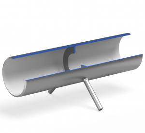
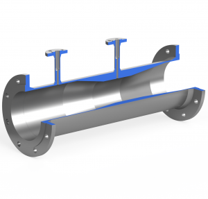
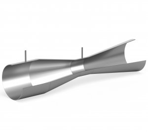
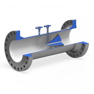
- Process industry and power plants: Level measurement in closed tanks with aggressive media, where hydrostatic transducers cannot be submerged. Flow measurement over venturi tubes, orifice plates and nozzles is also based on the differential pressure being proportional to the flow.
- Cleanrooms and laboratories: Control of positive or negative pressure between rooms to prevent particles or contaminants from moving in the wrong direction.
- Hydraulics: Monitoring of pressure drop across filters and pumps to anticipate wear conditions and avoid downtime.
Important factors when choosing a differential pressure gauge
- Measuring range (DP) and overload
Select a differential pressure range that covers both normal operating values and temporary peaks, but is not so wide that resolution is degraded. In addition, check that the maximum static pressure is above all possible test and shut-off pressures. - Accuracy and long-term stability
In critical control circuits, ±0.05 % of range is often required, while ±0.5 % is sufficient for visual filter monitoring. Also watch out for zero drift with large temperature variations. - Materials and temperature resistance
316L stainless steel diaphragms are standard, but highly corrosive media may require Hastelloy alloy or PTFE coating. Sealed impulse lines are a must in hot steam to protect the sensor. - Electrical interface and certifications
Process plants with explosion risk require ATEX or IECEx classification, and in safety circuits the sensor must fulfil SIL requirements (often SIL 2). - Service and calibration
Choose transducers with integrated shut-off valves or traditional three- or five-valve manifolds for easy pressure relief during zeroing and calibration.